


- All
- Product Name
- Product Keyword
- Product Model
- Product Summary
- Product Description
- Multi Field Search
Views: 0 Author: Site Editor Publish Time: 2026-04-14 Origin: Site
In 2026, structured cabling systems form the foundational infrastructure of modern intelligent buildings, data centers, and enterprise networks worldwide. With the widespread deployment of 10G/25G/40G BASE-T, high-power PoE++ (IEEE 802.3bt), and the integration of IoT and AI-driven networks, the performance and reliability of cabling systems have become more critical than ever. This guide provides a comprehensive, step-by-step framework for testing and certifying structured cabling systems in accordance with the latest international standards (ISO/IEC 11801, ANSI/TIA-568.2-D, ANSI/TIA-568.3-D) to ensure optimal performance, compliance, and long-term ROI across global projects.
Adhering to globally recognized standards is the cornerstone of reliable cabling testing in 2026. The following standards define the requirements for components, installation, and testing, ensuring interoperability and performance across different regions and vendors:
• ISO/IEC 11801-2017/Amd 2: The global benchmark for balanced twisted-pair and optical fiber cabling systems, covering performance requirements for copper (up to Cat8) and fiber (multimode and singlemode) cabling, including support for high-speed Ethernet and PoE++.
• ANSI/TIA-568.2-D: The North American standard (widely adopted globally) for copper cabling components and field testing, specifying test parameters, acceptance criteria, and methodologies for balanced twisted-pair cables (Cat5e to Cat8).
• ANSI/TIA-568.3-D: The international standard for optical fiber cabling systems, outlining requirements for fiber types, termination, and testing to support high-bandwidth applications in data centers and backbone networks.
• IEEE 802.3bt: The standard for Power over Ethernet (PoE++), governing the delivery of up to 90W of power over twisted-pair cabling, which requires specific testing to ensure compliance and safety.
• ANSI/TIA-606-B: The international standard for cabling administration, including labeling, documentation, and record-keeping—critical for post-installation maintenance and compliance audits.
Before testing, confirm the cabling media and category to select the appropriate test parameters and acceptance criteria, as defined by international standards. In 2026, the most commonly deployed media and categories include:
• Copper Cabling: Cat5e (largely obsolete for new installations, but still tested for existing systems), Cat6(supports up to 1Gbps), Cat6A (10GBASE-T standard, 500MHz), Cat7/Cat7A (shielded, up to 10Gbps at 600MHz), and Cat8 (shielded, up to 40Gbps at 2000MHz) for high-density data center applications.
• Fiber Optic Cabling: Multimode fiber (OM3, OM4, OM5—supporting 10Gbps to 100Gbps over short distances), singlemode fiber (OS1, OS2—supporting 10Gbps to 400Gbps over long distances), and MPO/MTP connectors for high-density backbone cabling in data centers.
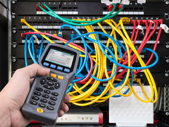
To ensure accurate and compliant test results, use certification-grade test equipment with Level III/IV accuracy, calibrated to international standards (e.g., ISO/IEC 17025). The following tools are required for comprehensive testing in 2026:
• Copper Certification Testers: Fluke DSX-8000, AEM TestPro, or WireXpert 5000—capable of testing up to 2000MHz (Cat8), measuring all critical parameters (including Alien Crosstalk), and generating compliant test reports.
• Fiber Optic Test Equipment: OTDR (Optical Time Domain Reflectometer, e.g., Fluke OptiFiber Pro) for backbone testing, Light Source & Power Meter (LSPM) for insertion loss testing, and a fiber inspection scope to verify clean, damage-free fiber endfaces.
• Calibration: All test equipment must be calibrated by an ISO/IEC 17025-accredited laboratory, with a valid calibration certificate. Calibration ensures test accuracy and compliance with international standards.
Proper documentation is essential for compliance, maintenance, and future troubleshooting. Prior to testing, prepare the following documents in accordance with ANSI/TIA-606-B:
• As-built drawings of the cabling system, including cable routes, patch panels, and work area outlets.
• A cable schedule detailing cable IDs, lengths, media types, and termination points.
• A patching matrix outlining the connections between patch panels, switches, and end devices.
• A test plan defining the scope of testing: 100% testing for critical links (e.g., data center backbones, server connections) and 20% random sampling for non-critical links (e.g., office workstations).
Ensure the testing environment meets international safety and performance standards to avoid interference and inaccurate results:
• Power off adjacent high-voltage systems, motors, and RF equipment to minimize electromagnetic interference (EMI), which can skew copper test results.
• Maintain a clean, dry testing area with a temperature range of 15–30°C and humidity ≤60%—environmental conditions specified in ISO/IEC 11801 for accurate testing.
• Use appropriate personal protective equipment (PPE) when working in data centers or industrial environments, including anti-static wristbands and safety glasses.
A thorough visual inspection is the first step in testing, as physical defects often cause performance failures. Follow ISO/IEC 11801 and TIA-568.2-D guidelines for inspection:
• Copper Cabling: Check for sharp bends (minimum bend radius ≥4× the cable diameter), proper cable support (no sagging), and non-overtightened cable ties (which can damage conductors). Verify that the untwisted length of pairs at terminations (jacks, patch panels) does not exceed 13mm—excessive untwisting causes crosstalk.
• Fiber Optic Cabling: Inspect fiber connectors for dirt, scratches, or damage using a fiber inspection scope. Ensure connectors are properly polished and seated securely in adapters. Check for excessive bending or kinking of fiber cables, which can cause signal loss.
• Termination: Confirm that all copper terminations follow the T568A or T568B wiring standard (consistent across the entire link) and that fiber terminations are clean and properly aligned.
The wiremap test verifies the physical connectivity of copper cables, ensuring there are no wiring errors. This test is mandatory for all copper links and is defined by TIA-568.2-D:
• Verify the absence of common wiring faults: open circuits, short circuits, reversed pairs, crossed pairs, and split pairs.
• Confirm that the same wiring standard (T568A or T568B) is used at both ends of the link—mixed standards cause connectivity failures and performance degradation.
• Record wiremap results for each link, as part of the final test report.
Performance certification is the core of copper cabling testing, verifying that the link meets the performance requirements of the specified category (e.g., Cat6A, Cat8) as defined by ISO/IEC 11801 and TIA-568.2-D. Test both Permanent Link (PL) (fixed cabling between patch panels and work area outlets) and Channel (CH) (permanent link plus patch cords at both ends).
The following parameters are mandatory for Cat6A copper cabling (10GBASE-T standard) and are defined by ISO/IEC 11801 and TIA-568.2-D. Acceptance criteria vary by cable category.
Parameter | Description | Acceptance Criteria (Cat6A Channel, 500MHz) |
Insertion Loss (IL) | Signal attenuation as it travels through the cable | ≤ 21.3 dB |
Return Loss (RL) | Signal reflection caused by impedance mismatches | ≥ 14.0 dB |
NEXT (Near-End Crosstalk) | Signal interference from adjacent pairs at the transmit end | ≥ 40.1 dB |
PS-NEXT (Power Sum NEXT) | Total crosstalk from all adjacent pairs | ≥ 37.1 dB |
ACR-N (Attenuation-to-Crosstalk Ratio) | Ratio of insertion loss to NEXT (indicates signal quality) | ≥ 18.8 dB |
ELFEXT (Equal Level Far-End Crosstalk) | Signal interference from adjacent pairs at the receive end | ≥ 24.6 dB |
PS-ELFEXT (Power Sum ELFEXT) | Total far-end crosstalk from all adjacent pairs | ≥ 21.6 dB |
Delay Skew | Time difference between the fastest and slowest pairs | ≤ 45 ns |
Propagation Delay | Time for a signal to travel the length of the link (100m max) | ≤ 548 ns |
DC Loop Resistance | Resistance of the conductor loop (100m max) | ≤ 18.8 Ω |
ANEXT (Alien NEXT) | External crosstalk between cable bundles | Mandatory for 10G/25G networks (meets TIA-568.2-D) |
Follow this structured process to perform copper cabling certification, in compliance with international standards:
1. Connect the main test unit to the patch panel in the telecom room (TR) and the remote unit to the work area (WA) outlet.
2. Select the appropriate test standard and cable category (e.g., ISO/IEC 11801 Cat6A Channel) on the test equipment.
3. Initiate the Auto-Test function— the instrument will automatically measure all required parameters and compare results to the selected standard.
4. Review the test results: the instrument will display aPASS or FAIL status, along with the location of any faults (distance from the main unit).
5. For FAIL results: Diagnose the issue (e.g., re-terminate the cable, replace damaged conductors, fix excessive untwisting) and re-test the link until it passes all parameters.
With the widespread adoption of PoE++ (IEEE 802.3bt) in 2026, testing for PoE compliance is mandatory for all copper links supporting PoE devices (e.g., IP cameras, access points, IoT sensors):
• Test DC resistance unbalance across pairs to ensure it does not exceed 3%—this ensures the cable can safely deliver up to 90W of power without overheating.
• Verify the cable’s temperature rise under full PoE load is within safe limits (as defined by IEEE 802.3bt) to prevent fire hazards or equipment damage.
• Confirm that the cable’s impedance is consistent across all pairs to avoid power delivery issues.
Fiber optic cabling testing focuses on signal loss and link integrity, in accordance with ISO/IEC 11801 and TIA-568.3-D. Two key tests are required for all fiber links: Insertion Loss (LSPM test) and OTDR test (for backbone links).
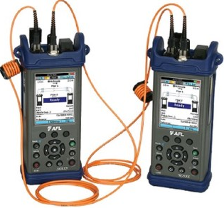
• LSPM Test (Light Source & Power Meter): The baseline test for all fiber links, measuring insertion loss (signal loss through the link). This test is required for all horizontal and backbone fiber links.
• OTDR Test (Optical Time Domain Reflectometer): A more advanced test for backbone fiber links, used to measure splice loss, connector loss, fault location (e.g., breaks, bends), and link length. This test is mandatory for long-haul and data center backbone links.
The following insertion loss limits are defined by ISO/IEC 11801 for common fiber types in 2026:
Fiber Type | Wavelength | Maximum Insertion Loss (dB/km) |
OM5 Multimode (50/125 μm) | 850 nm | 3.0 |
OM5 Multimode (50/125 μm) | 1300 nm | 1.0 |
OS2 Singlemode (9/125 μm) | 1310 nm | 0.4 |
OS2 Singlemode (9/125 μm) | 1550 nm | 0.3 |
Follow this process to perform compliant fiber optic testing, as outlined in ISO/IEC 11801 and TIA-568.3-D:
1. Clean Connectors: Use lint-free wipes and optical cleaning solution to clean all fiber connectors—dirty connectors are the most common cause of excessive insertion loss. Verify cleanliness with a fiber inspection scope.
2. LSPM Test: Connect the light source to one end of the fiber link (telecom room) and the power meter to the other end (work area or backbone termination). Select the appropriate wavelength (850 nm or 1310 nm for multimode; 1310 nm or 1550 nm for singlemode) and record the insertion loss. Ensure the loss is within the ISO/IEC 11801 limits.
3. OTDR Test: For backbone links, connect an OTDR to the fiber link using a launch fiber (to avoid dead zones). Run the test and analyze the OTDR trace to identify events: splices, connectors, bends, or breaks. Verify that splice loss and connector loss meet the following limits:
○ Splice loss: ≤0.1 dB (singlemode), ≤0.3 dB (multimode)
○ Connector loss: ≤0.5 dB per mated pair
4. Document all test results, including the OTDR trace (saved electronically) for future reference.
In 2026, advanced testing is increasingly required to ensure cabling systems support high-speed, mission-critical applications. These tests are recommended by ISO/IEC 11801 and TIA standards as best practices for enterprise and data center networks.
Alien Crosstalk (ANEXT) is interference between adjacent cable bundles, a critical issue for 10G/25G/40G networks. This test is mandatory for Cat6A, Cat7, and Cat8 cabling in bundled configurations (e.g., data center racks):
• Test ANEXT and Power Sum ANEXT (PSANEXT) in real-world conditions—cables bundled as they will be in the final installation.
• Ensure PSANEXT results meet the acceptance criteria defined in TIA-568.2-D for the cable category.
• If ANEXT fails, separate cable bundles or use shielded (FTP/SFTP) cabling to reduce interference.
To confirm the cabling system can support real-world high-speed traffic, perform end-to-end throughput testing using industry-standard tools:
• Use iperf3 (a globally recognized network testing tool) to run 10G/25G/40G end-to-end throughput tests for 24 hours.
• Verify key performance metrics: 0% packet loss, jitter < 10ms, and stable link speed (no drops below the specified bandwidth).
• This test is critical for data centers and enterprise networks supporting AI, IoT, and high-definition video applications.
Ensure the cabling system performs reliably in harsh environments, in compliance with ISO/IEC 11801’s environmental requirements:
• Test copper and fiber links near sources of EMI (e.g., motors, UPS systems, RF equipment) to confirm no performance degradation.
• For industrial or outdoor applications, verify that the cabling meets IP rating requirements (e.g., IP67 for waterproofing) and can withstand extreme temperatures (-40°C to 70°C).
• In fire-risk areas, confirm that cabling uses LSZH (Low Smoke Zero Halogen) insulation, as specified by international safety standards (e.g., IEC 60332-1).
Any link that fails certification must be remediated and re-tested to ensure compliance with international standards. Below are common failures and their solutions, as recommended by TIA and ISO/IEC guidelines:
Common Failures & Fixes
• NEXT/Return Loss Fail: Re-terminate the cable, ensuring the untwisted length does not exceed 13mm. Replace poor-quality jacks or patch panels that do not meet TIA/ISO standards.
• High Insertion Loss (Copper): Check for damaged conductors or excessive bending. Re-terminate or replace the cable if necessary.
• High Insertion Loss (Fiber): Clean connectors thoroughly, replace damaged fiber, or improve the bend radius (minimum 10× the cable diameter for multimode, 15× for singlemode).
• Delay Skew Fail: Use high-quality twisted-pair cable from a certified vendor. Avoid excessive untwisting at terminations.
• ANEXT Fail: Separate cable bundles by at least 150mm, use shielded cabling (FTP/SFTP), or route cables away from EMI sources.
• PoE++ Load Test Fail: Replace the cable with a higher-quality Cat6A/Cat8 cable that meets IEEE 802.3bt requirements. Check for loose terminations.
Re-test Requirement: All repaired links must pass a full certification test (all parameters) before being accepted. Partial testing is not compliant with international standards.
Comprehensive documentation is required to demonstrate compliance with international standards and to support future maintenance. Follow ANSI/TIA-606-B and ISO/IEC 11801 guidelines for documentation.
• Generate an electronic test report from the certification tester, which includes: link ID, test date, technician name, selected standard, all test parameters, PASS/FAIL status, and fault details (if any).
• Store the report digitally (cloud or server) and provide a hard copy for the client. Retain all test reports for ≥5 years—required for warranty claims and compliance audits.
• Ensure the report is signed by the testing technician and client to confirm acceptance.
• Update the as-built drawings to reflect the final cabling installation, including any changes made during testing and remediation.
• Maintain a label log detailing all cable IDs, termination points, and test results.
• Register the cabling system with the manufacturer to activate the standard 25-year warranty (common for ISO/IEC-certified systems).
To ensure long-term performance and compliance, implement a maintenance plan in accordance with ISO/IEC 11801 and TIA-606-B. This plan should include:
• Quarterly Maintenance: 10% sample testing of critical links (e.g., data center backbones, PoE-enabled links) to identify early performance degradation.
• Annual Certification: 100% re-certification of high-density areas (e.g., data center racks) and critical links to ensure ongoing compliance with international standards.
• Change Management: All moves, adds, or changes (MACs) to the cabling system must be re-tested and documented. This includes adding new work area outlets, changing patch cords, or re-terminating links.
• Regular Inspection: Visually inspect cabling, connectors, and patch panels quarterly to identify physical damage, dirt, or loose connections.
In 2026, structured cabling testing is a mandatory engineering process—required to ensure networks support 10G/25G/40G, PoE++, IoT, and AI workloads reliably across global projects. By following this step-by-step guide, adhering to the latest ISO/IEC and TIA standards, using calibrated certification tools, and maintaining complete documentation, you will deliver a high-performance, future-proof cabling infrastructure that meets or exceeds international requirements.
The global adoption of consistent standards means that a certified cabling system in one region will perform reliably in another, ensuring interoperability and reducing risk for multinational organizations. As technology evolves, staying updated on the latest international standards and testing methodologies will remain critical to delivering reliable, compliant cabling systems.
Always test to certify—not just to pass.

