


- All
- Product Name
- Product Keyword
- Product Model
- Product Summary
- Product Description
- Multi Field Search
Views: 0 Author: Site Editor Publish Time: 2025-10-22 Origin: Site
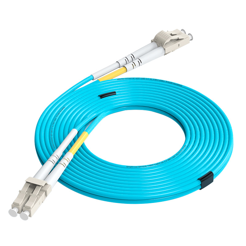
In modern communication networks, fiber optic patch cords serve as the core components for connecting fiber lines, with their performance directly impacting the stability and efficiency of data transmission. Imagine if the fiber endfaces fail to dock precisely—the light energy from the transmitting fiber cannot efficiently couple to the receiving end, leading to signal attenuation, packet loss, or even network outages. This is not just a technical issue but a pain point affecting applications like 5G, data centers, and fiber-to-the-home (FTTH). This article delves into the three-parameter standards for fiber optic patch cord endfaces (Radius of Curvature ROC, Apex Offset, and Fiber Height), helping you understand how these parameters ensure physical contact, achieving low insertion loss and high return loss. Whether you're an engineer or a procurement decision-maker, this guide provides practical insights.
The success of fiber optic line connections relies on the precise docking of two endfaces. Just like a precision lock and key, the fiber endfaces must "fuse into one" to maximize light energy coupling. Physical contact is the cornerstone of low insertion loss (IL) and high return loss (RL). If there are micron-level gaps between endfaces, reflected light will interfere with the signal, degrading performance.
The evolution of endface shapes has gone through three stages: PC (Physical Contact), UPC (Ultra Physical Contact), and APC (Angled Physical Contact). PC endfaces feature basic spherical polishing with RL around 40 dB; UPC optimizes the radius of curvature for RL up to 55 dB; APC introduces 8° angled polishing for RL as high as 65 dB. This progression stems from the need to suppress reflected light, especially in high-density data center environments.
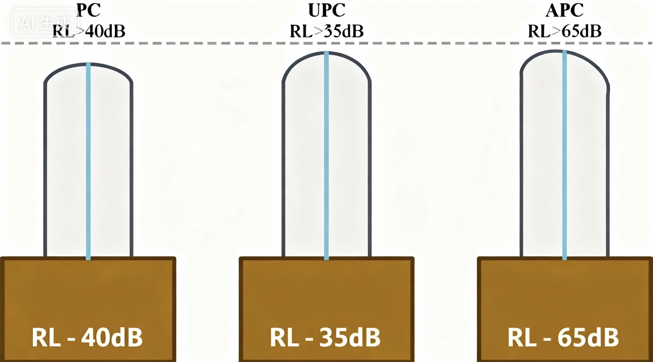
Figure 1 Types of Grinding for the End Faces of Optical Fiber Connectors
These endfaces are all spherically polished, but actual production cannot achieve perfection. The International Electrotechnical Commission (IEC) has established strict standards focusing on the three key parameters to ensure reliable physical contact under pressure.
Fiber optic patch cord endfaces are polished into spheres, but geometric parameters must be quantified to control quality. IEC standards (as shown in Table 1) define three critical metrics:
| Parameter | PC/UPC Type | APC Type | Description |
|---|---|---|---|
| Radius of Curvature (ROC) | 10~25 mm | 5~15 mm | Curvature of the endface arc, controlling deformation for contact |
| Apex Offset | ≤50 μm | ≤50 μm | Offset between the spherical apex and fiber axis, affecting alignment |
| Fiber Height | -250~+50 nm | -250~+50 nm | Height deviation of the fiber endface relative to the ferrule |
Radius of Curvature (ROC): The endface is polished into an arc shape, and the ROC value must be moderate. If too large (>25 mm), deformation under pressure is insufficient for contact; if too small (<5 mm), it risks crushing the fiber during repeated mating. PC/UPC prefers larger ROC for balanced durability, while APC requires smaller ROC to compensate for additional deformation from the angle.
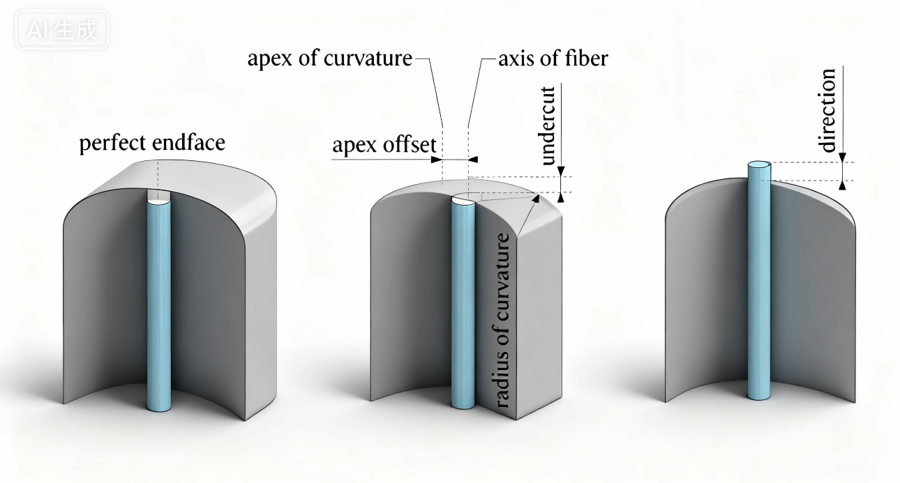
Figure 2 Fiber ribbon end face shape (diagram of three values)
Apex Offset: This refers to the deviation between the spherical apex and the fiber axis. Excessive offset causes endface deformation leading to fiber gaps, affecting contact. The standard upper limit of 50 μm is based on experimental validation: within this range, physical contact is reliable, avoiding additional losses.

Fiber Height: The fiber endface may protrude slightly (+) or recess (-) relative to the ferrule. Elastic deformation allows deviations within ±250 nm: minor recessions are compensated by ferrule deformation, and minor protrusions by fiber elasticity. Exceeding this range introduces air gaps, amplifying reflections.
These parameters are interconnected. Tools like interferometers enable precise inspection to ensure compliance with IEC 61755 standards.
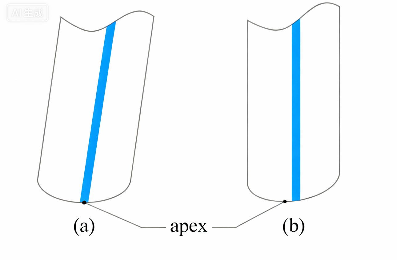
APC connectors are renowned for their 8° angled faces, which suppress reflections but introduce complexities. During polishing, ceramic ferrules are tilted in the polishing plate (as in Figure 4a) to form the angle; when inserted into the adapter, they become vertical (Figure 4b), shifting the apex away from the core.
When connecting two APC endfaces (as in Figure 5), apex misalignment requires greater deformation, hence the smaller ROC of 5~15 mm. A keyed pin indicates the angle direction, and its precision directly affects offset.

Figure 5: The matching condition between the two APC optical fiber connectors
Apex offset sources are diverse (as in Figure 6):
Polishing Angle Error (Δ): Offset d1 = R × Δ. For example, with R=10 mm and Δ=0.1°, d1=17.5 μm.
Pin Azimuthal Error (δ): Offset d2 = R × sin(8°) × sin(δ). In the same example, with δ=1°, d2=24.3 μm.
Total offset must be <50 μm, emphasizing precision manufacturing: polishing plate angle control, pin assembly accuracy, and adapter slot fit. Azimuthal errors arise from mechanical tolerances and require orthogonal experimental optimization.

Figure 6 The influence of various factors on the vertex offset at the end face of the optical fiber connector
These calculations reveal: While APC excels in RL, its manufacturing threshold is higher. Ignoring offset can amplify insertion loss by over 10%.
Spherical endfaces result from pressure polishing on a "soft" pad, where pad hardness, pressure, and polishing film roughness must be regulated. Multi-factor orthogonal experiments yield optimal parameters, ensuring >500 mating cycles durability.
For APC, additional considerations include angle precision (<0.1°) and pin azimuth (<1°). Without anti-reflective coatings, physical contact is key, making environmental adaptability crucial: under high temperature, humidity, or vibration, parameter deviations amplify risks.
Industry practices show that optimizing the three parameters can reduce average insertion loss to 0.1 dB and stabilize RL >60 dB. Changzhou Shenghao Intelligent Technology Co., Ltd. , a global leader in comprehensive cabling solutions, specializes in copper cables, fiber optics, data centers, and more. We employ advanced interferometers and automated polishing lines to ensure IEC compliance, serving FTTH, 5G base stations, and internet data centers. Visit www.zoracz.com to explore our fiber optic patch cord solutions and empower your network upgrades.
The three-parameter standards for fiber optic patch cord endfaces are the "guardians" of connection reliability. From PC to APC evolution, precise control of ROC, Apex Offset, and Fiber Height ensures physical contact stands firm in harsh environments. Understanding these not only enhances design capabilities but also optimizes procurement decisions.
In the digital wave, selecting compliant products is vital. Contact Changzhou Shenghao Intelligent Technology Co., Ltd. www.zoracz.com for customized consultations. We are committed to innovative cabling, empowering the telecom future. Your network deserves the best protection!

