


- All
- Product Name
- Product Keyword
- Product Model
- Product Summary
- Product Description
- Multi Field Search
Views: 0 Author: Site Editor Publish Time: 2026-07-31 Origin: Site
In the Fluke professional tests for the acceptance of structured cabling projects and daily link operation and maintenance, near-end crosstalk (NEXT) is the high-frequency parameter that is most likely to fail. A large amount of on-site test data shows that the basic parameters such as wiring diagrams, cable lengths, and signal attenuation of most faulty links are fully up to standard, except for the near-end crosstalk test which fails.
This fault is highly concealed and cannot be directly identified by the naked eye. It is also the core cause of the obstruction in the acceptance of high-end cabling systems of Category 6 and super Category 6, as well as the network operation lag and packet loss.
This article, based on the testing principles of Fluke DSX and DTX series equipment and first-hand construction and operation and maintenance experience, comprehensively analyzes the core reasons for the failure of near-end crosstalk, and provides precise troubleshooting ideas and standardized rectification plans.
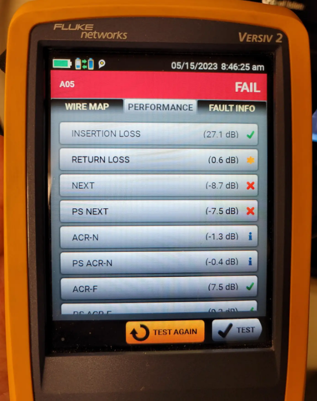
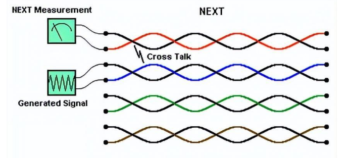
The standard network cable contains four pairs of twisted wires that are twisted together. The precise twisting process during cable production is mainly used to counteract the electromagnetic interference between the wire pairs and ensure stable signal transmission.
Near-end Crosstalk (NEXT) specifically refers to the phenomenon where, at the Near End of the network cable link test (the connection end of the Fluke tester host), when a certain pair of wires transmits high-frequency signals, the electromagnetic energy generated leaks to adjacent pairs, causing signal interference.
The test logic of the Fluke device is to detect the difference between the effective signal and the interfering signal, that is, the crosstalk margin.
The larger this value is, the better the link's anti-interference performance will be. When the value is lower than the industry standard threshold, the device directly determines that the NEXT test has failed. Compared with far-end crosstalk, near-end crosstalk has a more direct impact on network transmission. A slight over-limit can cause fluctuations in network speed, data packet loss, and increased latency. A severe over-limit can lead to the inability to negotiate gigabit and 10-gigabit bandwidths normally, resulting in link paralysis and failure to pass project acceptance.
According to the official fault data statistics of Fluke, over 90% of the failures in the NEXT test are not related to the quality of the cable itself. The root causes of the faults are mainly concentrated in four dimensions: construction and terminal connection techniques, accessory matching, wiring and laying, and hidden line faults. Among them, non-standard construction is the primary cause.
The anti-interference ability of twisted-pair cables is entirely dependent on the original twisted structure. During construction, disrupting the twisted state of the wire pairs is the main cause of excessive crosstalk and also the detail issue that is most easily overlooked by construction workers.
Common non-standard operations include three categories:
One is excessive stripping. When terminating crystal heads and information modules, the outer sheath of the network cable is stripped too long, causing the untwisting distance of the wire pairs to exceed the standard. The industry clearly stipulates that the untwisting length of high-end cables of category 6 and above must not exceed 13mm.
The second is to forcibly straighten the straight lines. To facilitate alignment and wire pressing, the twisted pair cables are overly stretched and straightened, completely destroying the precise twisting Angle and spacing of the cables when they leave the factory.
Thirdly, the wiring arrangement is loose. When the modules and crystal heads are terminated, the wire pairs are squeezed and deformed, and the arrangement is disordered, disrupting the electromagnetic balance between the wire pairs.
The characteristics of this type of fault are very distinct. The Fluke test report shows that the crosstalk value at the near end of the link is the worst. Through the HDTDX time-domain diagnosis function, the fault points can be precisely located at the positions of the joints and modules at both ends of the link.
For Category 6 and super Category 6 high-frequency and high-speed cabling systems, the electrical compatibility requirements for link accessories are extremely high. Fluke officially stipulates that the grade of the cabling link must be completely consistent with the grade of the matching accessories. It is strictly prohibited to use them in a downgraded or mixed manner, otherwise it will directly lead to excessive crosstalk parameters.
High-frequency fault scenarios on site include:
In the Super Category 6 (6A) cabling link, non-compliant crystal heads, information modules and couplers of ordinary Category 6 and Category 5 are illegally combined.
Uses substandard and unbranded accessories. The spacing of the metal spring pieces in such accessories is not standard and they lack electromagnetic shielding design, thus having inherent crosstalk defects.
The substandard non-standard patch cords used in the test and completion links were mixed, and the twisting process of the patch cords was rough, which became the crosstalk shortcoming of the entire link.
Most inferior accessories have no difference in appearance from compliant ones, but their electrical performance does not meet the standards, which is a typical source of hidden faults.
External force damage and complex environmental interference during the cable laying process can alter the internal physical structure of twisted-pair cables, disrupt the anti-interference system, and cause continuous over-limit NEXT.
On the one hand, there is the damage to cables caused by violent construction. Excessive bending of network cables, forceful squeezing, and overly tight binding of cable ties can lead to deformation of the internal wire pairs and deviation in spacing, completely losing their anti-interference ability.
On the other hand, there is the superposition of electromagnetic interference. Network cables are laid in parallel and bundled with strong power lines, distribution boxes, frequency converters, and high-power equipment at close range, continuously exposed to strong external electromagnetic radiation interference, which amplifies the crosstalk of internal wire pairs.
At the same time, excessive redundant reels in the link and disorderly winding of the lines will continuously accumulate electromagnetic interference, causing the crosstalk margin to continuously decline and eventually triggering the failure of the NEXT test.
Conventional wire sequence errors will directly lead to the failure of wiring diagram testing, but some hidden wire sequence problems will only cause excessive crosstalk and are very easy to be misjudged.
Among them, the most typical one is the pair separation fault. During construction, the core wires of different pairs were mistakenly crossed and terminated, completely disrupting the balanced transmission structure of the twisted-pair cable and causing continuous inherent crosstalk. Conventional on-off detection cannot identify it, and only the NEXT test will accurately report an error.
In addition, issues such as oxidation of link joints and module pins, dust adhesion, minor short circuits, as well as damage to the cable sheath, moisture absorption and water ingress, can alter the original electrical parameters of the line, causing abnormal electromagnetic transmission and indirectly leading to excessive near-end crosstalk values.
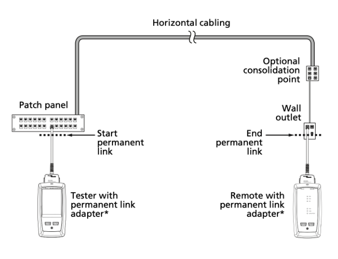
For the failure of the NEXT test, there is no need to blindly rework. Relying on the exclusive functions of the Fluke device, faults can be quickly located, significantly improving the efficiency of troubleshooting.
First, review the detailed test data, identify the faulty pairs that reported errors, and most of the over-standard issues on site are concentrated in pairs 4-5 and 7-8. Precisely narrow down the scope of the investigation.
Secondly, enable the HDTDX time-domain crosstalk analysis function. Locate the fault position through the equipment waveform. If the waveform peak appears at the 0-5 meter near end, it is determined to be a problem with the joint termination process. If the peak appears in the middle of the link, it is a problem of cable compression or external electromagnetic interference.
Finally, eliminate the false faults of the equipment, replace the original Fluke calibration jumpers and adapters for retesting, and avoid false alarms caused by faults in test accessories.
By combining the causes of various faults and corresponding standardized construction rectification techniques, it can be ensured that the link retest is 100% qualified
First, redo the termination process, strictly control the stripping length and untwisting distance, retain the original twisting state of the wire pairs, avoid straightening and squeezing the wire pairs, and standardize the T568B standard termination operation.
Second, unify the link accessories and strictly follow the principle of "matching at the same level". High-end links should use brand-compliant accessories in full, and avoid mixing and matching or inferior accessories.
Third, optimize the wiring environment, rectify bent, compressed or overly tightly bundled cables, reduce redundant reeled wires, maintain a safety distance of more than 30cm between network cables and strong current and high-power electromagnetic equipment, and use vertical crossing for cross-wiring. Fourth, fix hidden faults, investigate and rectify the problem of pair separation, clean and replace oxidized, damp or damaged connectors and cables to ensure the stability of the electrical performance of the link.
The failure of the near-end crosstalk (NEXT) test is essentially a detail flaw in the meticulous construction of the wiring project rather than a quality issue with the cable itself. On-site investigation and rectification should follow the priority of prioritizing termination processes, accessory matching as a supplement, optimizing the wiring environment, and providing a safety net for hidden faults. Relying on the professional detection function of Fluke equipment to accurately locate problems and implement standardized construction and rectification processes, not only can the project be quickly accepted, but also problems such as network packet loss, lag, and insufficient bandwidth can be eliminated from the root, ensuring the long-term stable operation of the cabling link.

