


- All
- Product Name
- Product Keyword
- Product Model
- Product Summary
- Product Description
- Multi Field Search
Views: 0 Author: Site Editor Publish Time: 2026-07-21 Origin: Site
In modern data center cabling and high-speed network architectures, optical fiber cables, with their advantages of high bandwidth and low loss, have become the core medium to replace traditional copper cables. However, in actual network deployment and link planning, the maximum transmission distance of optical fibers is not a fixed value but is subject to a combination of various physical and engineering factors. Understanding these factors is crucial for optimizing network performance, reducing construction costs and enhancing system reliability.
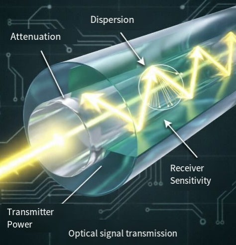
Loss is the most direct factor limiting the transmission distance of optical fibers. When optical signals propagate in optical fibers, their energy gradually weakens as the distance increases. When the signal attenuates to the point where it cannot be correctly identified at the receiving end, the communication will be interrupted.
· Material absorption and scattering: The material of optical fibers (such as quartz glass) itself will have a weak absorption of light. Meanwhile, the inhomogeneity of the material's microstructure will lead to Rayleigh scattering, which is an inherent source of loss in optical fibers.
· Wavelength selection: Different working wavelengths result in significant differences in loss. For instance, the typical attenuation of single-mode optical fibers at the 1310nm window is approximately 0.30 to 0.40 dB/km, while it drops as low as 0.20 to 0.22 dB/km at the 1550nm window. Therefore, for long-distance transmission, a wavelength of 1550nm is usually preferred.
· Engineering margin: In actual wiring, additional losses will occur at fiber optic fusion joints, connectors, and bends. Professional link design must reserve an engineering margin of 2 to 3dB to cope with temperature fluctuations and component aging.
If loss makes the signal "weaker", then dispersion makes the signal "blurred". Dispersion can cause the broadening of optical pulses during transmission, thereby inducing minimum interference and limiting the system's bandwidth and transmission distance.
· Mode dispersion: Mainly exists in multimode optical fibers. Due to the fact that light of different modes travels different path lengths in optical fibers, the time it takes to reach the receiving end varies, resulting in pulse broadening. This is also the core reason why multimode fibers are typically only used for short-distance interconnection in data centers. 1
· Chromaticity dispersion: In single-mode optical fibers, since the light source is not an absolutely single wavelength, the propagation speeds of light of different wavelengths are different, thus causing dispersion. In high-speed transmission systems of 10Gbps and above, the distance limitation of dispersion is particularly obvious, and it is usually necessary to introduce a dispersion compensation module (DCM) to correct the signal.
The ultimate distance of an optical fiber link largely depends on the performance matching of the optical modules at both ends.
· Transmitted optical power: The greater the average optical power coupled into the optical fiber at the transmitting end of the optical module, the farther the signal can be transmitted.
· Receiving sensitivity: The minimum optical power at which the receiving end can correctly decode the signal. The higher the sensitivity (the smaller the value), the weaker the signal can be received, thereby extending the transmission distance.
· Link budget: When engineers design a network, they calculate the theoretical maximum distance through the formula "(transmission power - reception sensitivity)/fiber attenuation coefficient", and then select the appropriate optical module (such as SR, LR, ER, ZR, etc. specifications) based on this.
The type of optical fiber itself determines the upper limit of its transmission characteristics. Single-mode optical fiber (SMF) is the preferred choice for long-distance transmission in metropolitan area networks and backbone networks due to its extremely small core, allowing only one mode of light to propagate and completely eliminating mode dispersion. Although multimode fiber (MMF) is less costly and easier to terminate, it is limited by mode dispersion and is more suitable for short-distance applications. In addition, the manufacturing purity of optical fibers, the quality of the coating, and the laying process during construction (such as avoiding excessive bending) will all directly affect the final transmission performance.
In conclusion, the maximum transmission distance of optical fibers is jointly determined by loss, dispersion, equipment performance and the type of optical fiber. When designing a comprehensive cabling scheme, only by fully considering these variables and making a strict link budget can an efficient and stable optical fiber network be constructed.
Specification of optical module | Typical rate | Compatible optical fiber type | Typical maximum transmission distance | Core application scenarios |
SFP-1000-SX | 1G | Multimode (MMF) | 550m (OM3/OM4) | Local area network, short-range access |
SFP-1000-LX | 1G | Single-mode (SMF) | 10km | Campus network and metropolitan area access |
SFP+-10G-SR | 10G | Multimode (MMF) | 300m (OM3/OM4) | Interconnection between data center cabinets |
SFP+-10G-LR | 10G | Single-mode (SMF) | 10km | Data center core layer, metropolitan area network |
SFP28-25G-LR | 25G | Single-mode (SMF) | 10km | 5G fronthaul and data center upgrade |
QSFP28-100G-SR4 | 100G | Multimode (MMF) | 100m (OM3/OM4) | High-density data center core |
QSFP28-100G-LR4 | 100G | Single-mode (SMF) | 10km | Interconnection of backbone networks and long-distance data centers |


When designing robust data center cabling or enterprise networks, maximizing transmission distance requires a precise balance of attenuation, dispersion, and transceiver performance.
At ZORA(www.zoracz.com), we understand that every decibel counts. Whether you are deploying standard SFP+ modules for 10G LANs or high-density QSFP28 solutions for 100G backbone links, our comprehensive range of fiber optic cabling and transceivers is engineered to meet your exact link budget requirements.
Don't let signal degradation compromise your network. Explore our premium selection of single-mode and multimode fiber solutions to build a future-proof infrastructure.

