


- All
- Product Name
- Product Keyword
- Product Model
- Product Summary
- Product Description
- Multi Field Search
Views: 0 Author: Site Editor Publish Time: 2026-09-09 Origin: Site
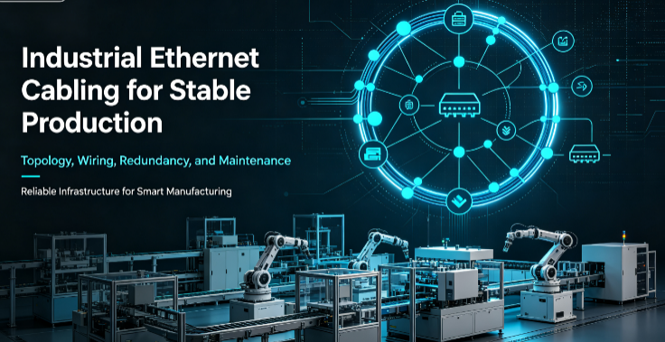
In the current era of the full implementation of intelligent manufacturing and Industry 4.0, automated production lines have long transcended the single-machine operation mode and formed a networked production system where PLCS, servo drivers, industrial robots, AGVs, and visual inspection equipment are interconnected. As the core "digital nerve" for data transmission, equipment linkage and real-time control on production lines, the stability of the wiring system of industrial Ethernet directly determines the startup rate, production accuracy and operation and maintenance efficiency of the production line.
Unlike commercial office networks, production line sites are filled with harsh working conditions such as high-frequency electromagnetic interference, mechanical vibration, sudden temperature changes, oil and dust, and repeated cable bending. Ordinary cabling solutions are prone to problems such as packet loss, delay, disconnection, and signal attenuation, which directly lead to equipment alarms, production line shutdowns, and data confusion, causing irreversible production losses.
High-stability industrial Ethernet cabling is never merely about "pulling and wiring", but rather a systematic project that encompasses topology planning, cable selection, standardized construction, redundancy protection, acceptance and operation and maintenance. This article, based on practical experience from industrial sites, comprehensively dissects the construction logic and key points of implementation of high-stability industrial Ethernet cabling systems for automated production lines.
Most production line networks are unstable and faults occur frequently. The root cause is not insufficient equipment performance, but the wiring system does not meet the working conditions of industrial scenarios. The core pain points are concentrated in four aspects:
• Severe environmental interference: Strong electromagnetic radiation generated by power cables on production lines, frequency converters, and welding machines can interfere with the signal transmission of network cables, causing packet loss, delay, and jitter. The alternating high and low temperatures in the workshop and the corrosion caused by oil stains will accelerate the aging and damage of ordinary cables.
• Poor physical tolerance: The cables of mechanical arms, AGVs, and mobile workstations are constantly bent, stretched, and rubbed back and forth. Ordinary network cables are prone to breakage and damage to the outer sheath, leading to line faults.
• The architecture design is unreasonable: the topology is chaotic and there is no redundant design. A single-point line failure directly leads to the paralysis of the entire production line, which cannot meet the continuous production requirements.
• Non-standard construction: Mixed laying of strong and weak electricity, incorrect grounding, insufficient bending radius of cables, and loose crimping of joints, which have buried long-term hidden faults and are extremely difficult to troubleshoot.
Therefore, the core objective of building a highly stable cabling system is to be resistant to interference, withstand working conditions, have low failure rates, be easy to operate and maintain, and be redundant, thereby thoroughly consolidating the stable foundation of industrial networks at the physical layer.
The stability of the wiring system is determined from the topology planning stage. Industrial Ethernet is strictly prohibited from being networked at will. It is necessary to match the corresponding topology structure based on the production line scale, real-time requirements, and reliability level, and at the same time adopt a standardized hierarchical architecture.
The redundancy capabilities, real-time performance, and scalability of different topologies vary greatly, and the applicable scenarios are clear:
• Ring Topology (preferred for high-reliability core scenarios) : Supports MRP ring network redundancy protocol. Single-point line or equipment failures can quickly self-heal without the risk of network disconnection, and the self-healing time can be controlled within milliseconds. It is suitable for production lines with extremely high requirements for continuity and real-time performance, such as automotive welding and assembly, chemical industry, and precision processing, and is the mainstream topology of high-end automated production lines.
• Star topology (suitable for small and medium-sized production lines) : Simple structure, flexible deployment, convenient troubleshooting, single node failure does not affect the overall network, and high cost performance. It is suitable for small and medium-sized standardized production lines such as 3C electronics and small household appliance assembly, and does not require complex redundancy scenarios.
• Tree topology (Cross-regional networking in large factory areas) : Extended from the star topology hierarchy, it is suitable for large factories with large areas and multiple zones. It can achieve unified networking across workshops and regions, with clear hierarchy and convenient for zonal operation and maintenance.
Uniformly adopt a three-level architecture of core layer - aggregation layer - access layer to achieve standardized and modular cabling.
• Core layer: Deployed in the computer room, it adopts industrial core switches and is responsible for data forwarding throughout the entire plant. Single-mode optical fibers are preferred for the backbone link to avoid signal attenuation issues during long-distance transmission.
• Aggregation Layer: Deployed in the weak current rooms of each workshop and the central control cabinets of production lines, it aggregates data from single or multiple production line devices. It adopts industrial management switches, supports VLAN division and QoS priority scheduling, isolates control data from ordinary data, and ensures the real-time performance of industrial control signals.
• Access layer: Deployed at production line workstations and beside equipment, it connects to terminals such as PLCS, servos, robots, and sensors nearby. Industrial switches are installed on DIN rails, making it suitable for narrow installation scenarios in workshops.
Commercial cables are strictly prohibited in industrial scenarios. All wiring hardware must meet industrial standards such as wide temperature range, anti-interference, wear resistance, and tensile resistance. Different types of cables should be precisely matched for different scenarios.
• Fixed workstation wiring: Industrial super Category 5 / Super Category 6 shielded twisted pair cables (S/FTP, F/FTP) are preferred. 24AWG solid copper wires are used, combined with high-density shielded nets. The outer sheath is made of oil-resistant and chemically resistant TPE/PUR material. The operating temperature range covers -40℃ to +80℃, effectively resisting electromagnetic interference and environmental corrosion in the workshop. Category 5e is compatible with 100Mbps bandwidth devices, while Category 6E supports gigabit transmission and is suitable for high-speed data acquisition and visual inspection equipment.
• Wiring for mobile equipment: AGVs, robotic arms, and reciprocating workstations must use highly flexible drag chain cables, which have the ability to withstand tens of millions of bends, are tensile, torsional, and wear-resistant, and prevent cable breakage and core short circuits caused by frequent movement.
• Long-distance/cross-regional cabling: With a transmission distance exceeding 100 meters, cabling across workshops and buildings, the entire process uses single-mode optical fiber, free from electromagnetic interference, with a long transmission distance and no bandwidth bottleneck, completely solving the problems of limited transmission distance and signal attenuation of copper wires.
• M12 industrial aviation connectors are preferred for equipment terminals: D-code is compatible with 100M devices, X-code is compatible with 1G devices, waterproof, dustproof and anti-loosening, suitable for production line vibration conditions, eliminating the problems of loose and poor contact of ordinary RJ45 crystal heads. Industrial-grade shielded RJ45 connectors can be used at the cabinet and patch panel ends.
All the supporting accessories are of industrial grade: shielded patch panels, industrial waterproof network cable sockets, metal shielded cable trays, and dedicated grounding terminals, ensuring the integrity of the entire system's shielding and preventing interference from entering due to single-point shielding failure.
No matter how good the hardware and architecture are, if the construction is not standardized, all the efforts will be in vain. Industrial Ethernet cabling has strict construction standards. All details directly affect the long-term stability of the network. The core construction norms are as follows:
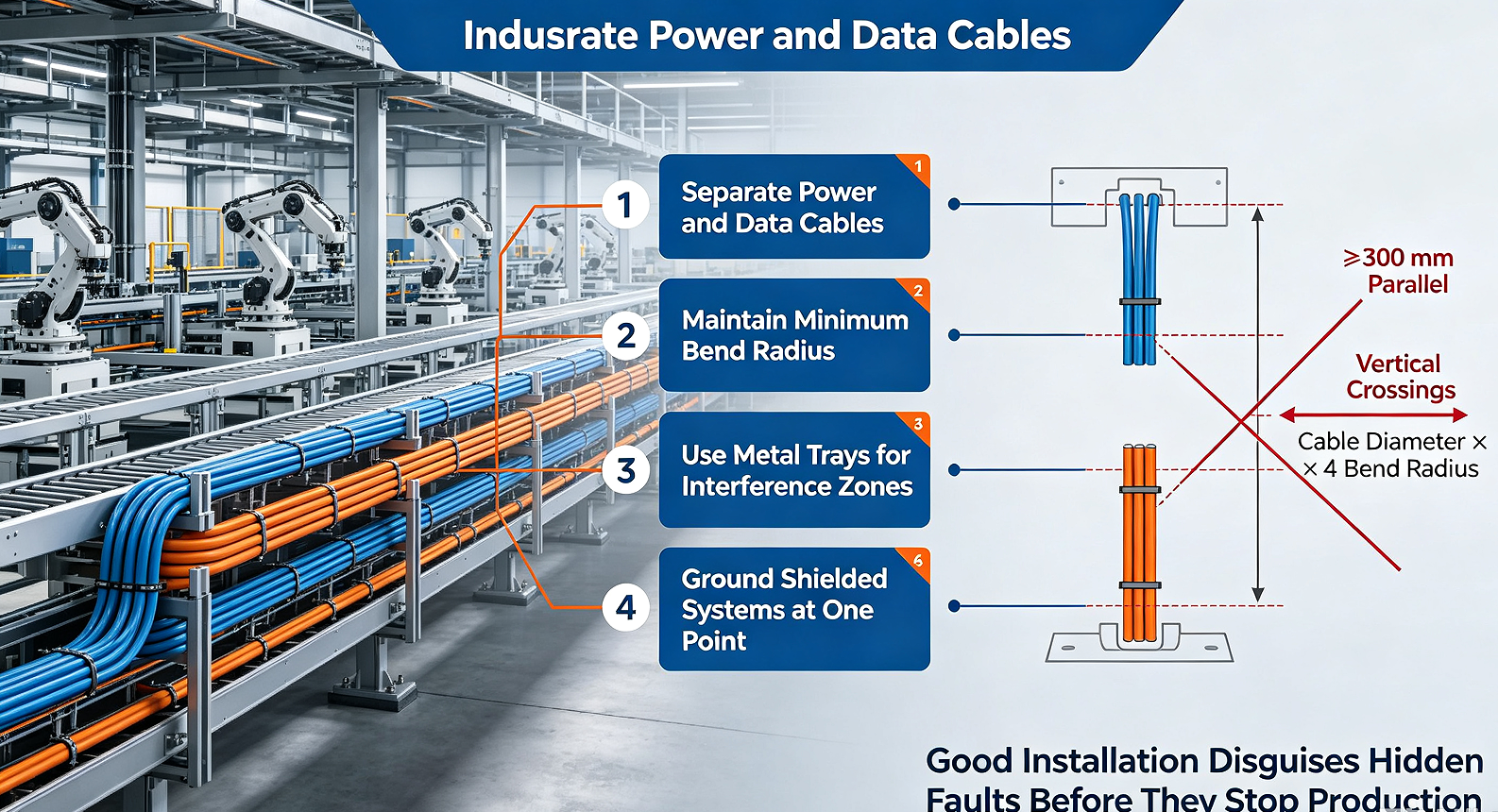
This is the core key to anti-interference! Industrial network cables and power cables (strong current) must not be laid together: when laid in parallel, the time interval should be no less than 30cm; when laid in a cross pattern, they must be crossed vertically with a spacing of no less than 10cm. For densely populated areas that cannot be avoided, metal channels and metal pipes should be used for separate isolation and shielding to completely block strong electric electromagnetic interference.
• Strictly control the bending radius of cables: The bending radius of shielded twisted-pair cables should be no less than 4 times the outer diameter of the cable. The bending radius of optical fibers should follow the equipment standards to prevent excessive bending from damaging the internal core wires and shielding layer.
• Wiring standards for drag chains: Cables should be arranged in layers within the drag chain without cross-entanglement. Sufficient movement allowance should be reserved to prevent the cables from being pulled or squeezed during the reciprocating motion of the equipment. The two ends of the drag chain are firmly fixed to reduce cable wear.
• Cables are securely and neatly fixed throughout the process: They are laid along the cable tray and cable trough. Suspended cables must be fixed to prevent cable shaking and loose joints caused by equipment vibration. The exposed cables in the workshop should be well protected to avoid being scratched by oil stains and sharp objects.
The core of the shielding system is full shielding and single-point grounding to eliminate ground loop current interference: the shielding layers of all shielded cables, connectors, and patch panels are fully connected without any breaks or exposed parts. The shielding layer is only grounded at a single point at the core end of the computer room, with the equipment end suspended to prevent the formation of a potential difference due to grounding at both ends and the generation of circulating current interference signals. At the same time, ensure that the grounding resistance is ≤4Ω, and the grounding line is independent without series connection.
Automated production lines aim for continuous and uninterrupted operation. The wiring system must be designed with redundancy to avoid overall downtime caused by single-point line or equipment failures.
• Link Redundancy: Core equipment and key workstations adopt dual-link cabling, combined with ring Network redundancy protocols (MRP/RSTP). When the main link fails, the backup link switches within milliseconds without any perceptible disconnection, ensuring the continuous operation of the production line.
• Equipment redundancy: The core and aggregation switches adopt dual power supply redundancy to prevent power outages and network disconnections caused by single power supply failures. The key industrial control network adopts a dual-network redundancy architecture to further enhance reliability.
• Network isolation protection: The control network, data acquisition network, and office network are physically and logically isolated through VLAN division to prevent fluctuations in the office network and external network attacks from affecting the core industrial control network. Through QoS Settings, priority is given to ensuring the real-time control data transmission of PLC, servo and robot, eliminating the equipment delay and loss of control caused by the occupation of bandwidth by big data.
After the wiring system is set up, standardized acceptance and regular operation and maintenance are the guarantees for long-term stable operation and can prevent frequent hidden faults in the later stage.
• Link performance testing: Professional cable testers are used to detect attenuation, crosstalk, return loss, and transmission delay to ensure compliance with industrial Ethernet transmission standards and no signal anomalies.
• Redundant function test: Manually disconnect the main link and main power supply to test the redundant switching speed and network stability, ensuring no network disconnection and no device alarm.
• Grounding and shielding test: Check the integrity of the shielding layer and the grounding resistance value to prevent shielding failure and poor grounding issues.
• Topology and Label acceptance: Verify that the network topology is consistent with the design plan. All cables, ports, and devices should be uniformly labeled, clearly indicating the point location, purpose, and number to facilitate later operation and maintenance troubleshooting.
• Regular inspection: Check the outer sheath of the cables, the tightness of the joints, and the fixation of the cable trays every month. Focus on inspecting the wear and aging of the drag chains and cables of mobile equipment.
• Data monitoring: By monitoring port traffic, packet loss rate, and delay data through the background of industrial switches, link abnormalities can be predicted in advance to achieve pre-fault detection.
• Archive retention: Complete retention of topology diagrams, wiring drawings, and test reports ensures that subsequent renovations, expansions, and fault detections are based on solid evidence, preventing blind construction.
The core of high-stability industrial Ethernet cabling for automated production lines does not lie in "using the best cables", but in scenario adaptation, reasonable architecture, construction standards, redundancy as a safety net, and standardized operation and maintenance. From the initial topology planning and precise hardware selection, to the mid-term standardized construction and anti-interference protection, and then to the later acceptance and operation and maintenance as well as redundancy optimization, each link is closely linked. Only in this way can the pain points of packet loss, disconnection, fluctuation and frequent faults in industrial field networks be thoroughly solved.
A qualified industrial Ethernet cabling system can not only ensure the high-precision and continuous production of the current production line, but also adapt to the later equipment expansion, production line transformation and intelligent upgrade, providing a long-term and stable network foundation for the digital and intelligent transformation of the factory.

